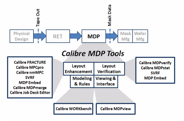
Siemens’ Calibre CAD suite incorporates a number of diverse tools for mitigating and predicting manufacturing imperfections generated during the fabrication of optical and electronic components. This overview page is meant to give a brief introduction to the stages through which each design must pass from circuit schematic to finished, physical semiconductor chip, and the roles these tools play at each stage. Figure 1 shows the entire Calibre tool flow (image taken from Reference 1).

In its ‘Higher Education Program’, under the heading of Calibre Manufacturing tools, the Siemens company groups two tool types: Resolution Enhancement Technology (RET) and Mask Data Preparation (MDP), the latter including the company’s FRACTURE modules.
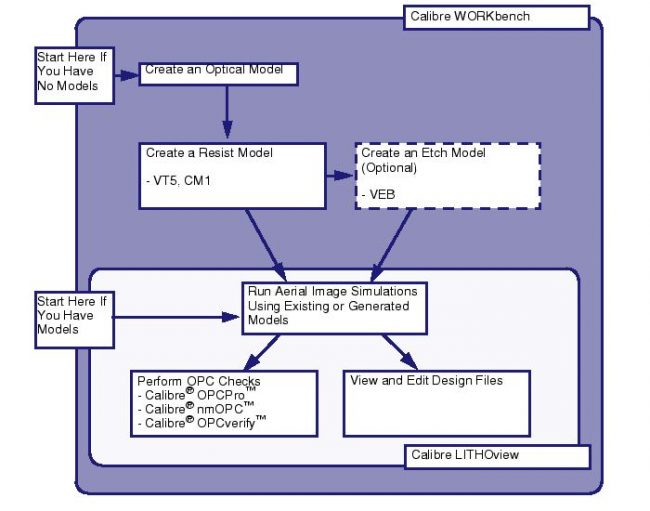
The tool flow from the student’s schematic and layout environment through to the finished device as handled by the Calibre CAD suite is shown in Figure 2.
Calibre RET Tools
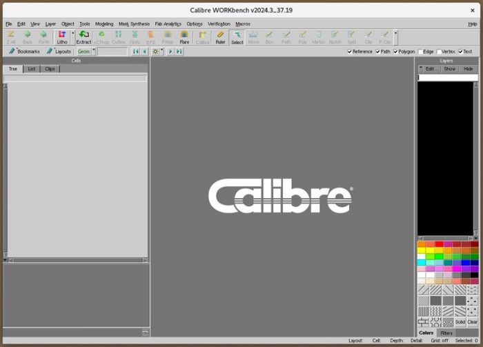
This group includes the main windows LITHOview and WORKbench. In these windows, a user may invoke the different tools or custom scripts to manipulate layout files or generate etching and resist pattern models.
| Calibre Tool Name | Function | Start Command |
| LITHOview | This is a model and design-based simulator for the following steps:
| calibrelv |
| WORKbench | Similar in nature to LITHOview, WORKbench also adds a model creation suite that does the following:
| calibrewb |
For productive use of these Calibre RET CAD tools, the following are recommended:
- Calibrated optical and resist models for the process of choice;
- A design file on which to run simulations;
- Familiarity with these Calibre viewers or tuning tool flows and OPC corrections; and
- Familiarity with Standard Verification Rule Format (SVRF) and the languages used by the particular tools.
It is possible to use the RET Flow Tool without these files or knowledge, but a mismatch between layouts, models, and setup files will produce poor results.
Calibre MDP Tools
The Calibre Mask Data Preparation suite is a collection of command-line-based tools used to generate, correct, verify and analyse photomask layouts. There is a viewer at the heart of the RET and MDP suites, called Calibre DESIGNrev, around which the more sophisticated editors/viewers are built.
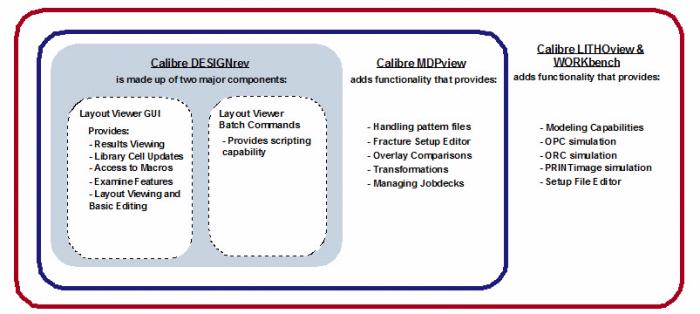
| Calibre Tool Name | Function | Start Command |
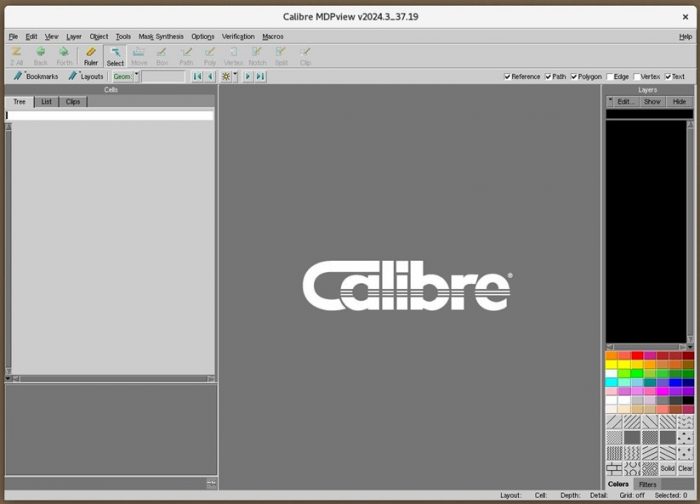
| MDPviewer | A GUI Interface that allows users to run Calibre FRACTURE tools, the DESIGNrev rule checking, Tcl programming language scripts or macro commands. | calibremdpv |
A special subset of Calibre MDP tools convert layer data into formatted data for specific manufacturers. These tools contain the word FRACTURE in their titles.
The FRACTURE toolset: A user defines as input to the FRACTURE Standard Verification Rule Format (SVRF) a rectangular section of a Calibre polygon layer. The polygons on this layer are optionally modified and converted to trapezoids. The polygons or trapezoids are then transformed to new co-ordinate and unit systems, and rearranged into the hierarchy of the requested format. These polygons or trapezoids are finally output in the FRACTURE format.
The SVRF rule file used to invoke this fracturing software must conform to all the requirements of such an SVRF rule file. For a complete description of these requirements, refer to the Standard Verification Rule Format (SVRF) Manual (Reference 5) that accompanies each release of Siemens’ Calibre suite.
Note that the supported versions of each format depend upon the Calibre release version.
| Specific FRACTURE Tool | Supported Format(s) |
| FRACTUREc | Micronic |
| FRACTUREh | Hitachi |
| FRACTUREj | JEOL |
| FRACTUREm | MEBES |
| FRACTUREt | Nuflare |
| FRACTUREn | Nuflare MBF |
| FRACTUREv | OASIS.MASK |
| FRACTUREp | OASIS.MAPPER |
| FRACTUREi | OASIS.MBW |
References
All these references are supplied with an installation of Siemens’ Calibre.
- “Calibre MDPview User’s and Reference Manual, Software Version 2024.3”.
- “Calibre Mask Data Preparation User’s and Reference Manual, Software Version 2024.3”.
- “Calibre WORKbench User’s and Reference Manual, Software Version 2024.3”.
- “Calibre WORKbench: RET Flow Tool User’s Manual, Software Version 2024.3”.
- “Standard Verification Rule Format (SVRF) Manual, Calibre 2024.3”.
